If you’ve ever worked with brushless DC (BLDC) motors, you’ve probably experienced that tiny, annoying, uneven jolt when you first turn the power on—instead of a smooth, seamless spin. That little hiccup isn’t random; it’s what we in the motor industry call cogging torque. As a supplier that’s shipped tens of thousands of BLDC motors to industrial, automotive, and consumer electronics customers over the past eight years, I’ve lost count of how many times engineers have stopped mid-conversation to ask, “Wait, what is that exact cogging torque thing, and how do I fix it?” Today, I’m breaking this down in plain, practical terms—no overly complex math, just the real-world stuff that matters when you’re designing a product that needs to run quiet, consistent, and reliable. Brushless Dc Motor
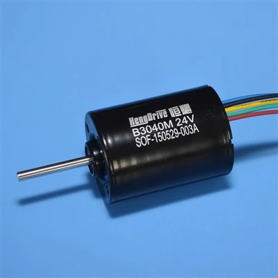
Let’s start with the basics, because cogging torque isn’t a flaw in the BLDC motor itself—it’s a side effect of how these motors are built. Unlike brushed DC motors, which use physical brushes and a commutator to switch current between rotor windings, BLDC motors have a permanent magnet rotor on the inside and a set of stationary copper windings (called stator teeth) on the outside. Every one of those stator teeth creates a small magnetic pull toward the permanent magnets on the rotor. When the rotor spins, each magnet passes a stator tooth one by one, and as they get closer, that pull gets stronger, peaks at the exact midpoint between two teeth, and drops off as they pass. That cyclic, alternating pull is cogging torque. It’s a reactive torque—meaning it doesn’t require any current to flow through the windings to show up; it’s just magnetic attraction between the rotor’s magnets and the stator’s iron teeth, even when the motor is turned off.
I remember a customer from a medical device company reaching out to me three years ago, panicking because their new insulin pump motor was making a click every few seconds. They’d tested a competitor’s motor and didn’t have the issue, but their design needed a smaller footprint, so they’d come to us for a custom unit. “The motor is only 10mm wide,” their engineer said. “If it’s jittering, our pump will be inaccurate, and that’s a safety issue.” When we tested their prototype, we confirmed the problem was cogging torque—not the motor’s speed control or electrical design. That’s when I realized how misunderstood this phenomenon can be: it’s not just a “noise issue” for power tools or small appliances; it can derail critical applications where even a tiny amount of torque ripple is a dealbreaker.
So, why is cogging torque a bigger deal for BLDC motors than other types? Let’s compare it to something more familiar: stepper motors. Steppers are designed to have small, predictable torque steps to move in precise increments, but that intentional “stiction” is actually a form of controlled cogging. BLDC motors, on the other hand, are built to run smoothly at high speeds, so that same cyclic pull is unwanted. It causes two main problems: first, noise and vibration, which is a headache for consumer products like refrigeration compressors, drone motors, and medical devices that need to be quiet. Second, torque ripple—uneven power delivery that can make a motor stall at low speeds, or cause wear on moving parts over time. That’s why, when you’re specifying a BLDC motor, you can’t just look at power output or size; cogging torque has to be on your checklist.
Now, let’s get into what actually causes cogging torque, beyond just “magnet and teeth pull.” There are three key design factors that determine how much cogging torque a motor will have, and this is where our team as a supplier really shines—because we adjust these factors to fit each customer’s needs, instead of using a one-size-fits-all design.
First, the number of rotor pole pairs and stator teeth. It’s a simple rule: cogging torque is smallest when the least common multiple (LCM) of the stator tooth count and rotor pole count is as large as possible. For example, a common small BLDC motor has 12 stator teeth and 8 pole pairs. The LCM of 12 and 8 is 24, so the cogging torque cycles once every 24 rotor steps. If we used a different combination, say 9 teeth and 6 poles, the LCM is 18—smaller, so more frequent, larger torque dips. That might not matter for a fan motor, but it’s a big problem for a robotics joint motor that needs consistent motion. Our engineers run simulations for every custom motor we build to pick the pole-teeth pair that minimizes cogging for your application, not just standard industry specs.
Second, the shape and size of the permanent magnets. Most BLDC motors use neodymium iron boron (NdFeB) magnets because they’re strong and small, but how they’re shaped and placed makes a huge difference. If a magnet is perfectly rectangular, the magnetic pull on the stator teeth is sharp and cyclic, leading to high cogging. We often use chamfered (beveled) or curved magnet edges, or even skewed magnets—twisting each magnet slightly along the rotor axis—to smooth out that pull. A customer building high-end electric skateboard motors came to us a year ago, saying their motors would vibrate so much at 20 mph that riders reported hand fatigue. Adjusting the magnet skew from 0 degrees to 12 degrees cut their cogging torque by 40%—enough to eliminate the vibration entirely, without increasing the motor’s cost or size.
Third, air gap uniformity. The air gap is the tiny space between the stator teeth and the rotor magnets, and if it’s not perfectly round—if one side is narrower than the other—the magnetic pull becomes uneven, leading to higher cogging. When we machine stator cores and assemble rotors, we use high-precision CNC equipment to keep the air gap consistent within 0.02mm across the entire rotor. For applications like aerospace actuators, where even a 0.1mm gap difference can cause significant cogging, we use laser alignment to make sure every part fits exactly as designed.
Here’s a common myth I hear all the time: “Cogging torque is unavoidable, so I just have to accept whatever comes with a standard motor.” That’s partially true for off-the-shelf BLDC motors—most mass-produced units have cogging torque ratings of 5-10% of their rated torque, which is fine for things like box fans or vacuum cleaners that don’t need super smooth motion. But for 60% of the customers we work with, that’s not enough. A 2022 study from the International Energy Agency found that high-cogging BLDC motors contribute 15-20% more long-term energy waste in variable-speed applications, because the uneven torque forces the motor to draw extra current to compensate for the dips. For that same reason, many industrial automation customers specify cogging torque limits of less than 2% of rated torque for material handling conveyors, where consistent speed means lower maintenance and longer equipment life.
A recent project that still sticks with me is a customer making exoskeletons for physical therapy. Their motors run at low speeds (less than 100 RPM) and have to deliver precise torque to support a patient’s limb—any jitter could cause discomfort or even injury. They tried three standard BLDC motors before coming to us; all had cogging torque that was 7% of their rated torque, leading to unsteady motion at low speeds. We designed a custom motor with 18 stator teeth and 12 pole pairs, curved magnets, and a custom winding pattern that reduced cogging torque to 1.2% of rated torque. Within a month, they tested the prototype and reported that the motion was so smooth, patients didn’t notice the motor at all. That’s the difference between understanding cogging torque as a problem to fix and seeing it as a design variable to optimize.
Now, how do you measure cogging torque, if you’re working with a motor? The standard test is simple: you run the motor without power, use a torque sensor to measure the force needed to spin the rotor through one full 360-degree rotation, and the peak-to-peak difference in that force is the cogging torque. For a standard motor, this is usually listed in the datasheet, but many suppliers don’t include it unless you ask. That’s a red flag—cogging torque is a critical performance parameter, especially for low-speed, high-precision applications. When you review a BLDC motor datasheet, look for terms like “peak cogging torque,” “cogging torque ripple,” or “static torque ripple”; if those numbers aren’t listed, reach out to the supplier and ask for them. We always include this data on every custom motor we provide, and we’re happy to run the test for standard units too, no extra charge.
Another way to mitigate cogging torque, if you can’t adjust the motor design, is to use motor control algorithms. Field-oriented control (FOC) is the standard for modern BLDC motors, and advanced FOC software can compensate for cogging torque by adjusting the current to the windings in real time, smoothing out the torque dips. But this is a workaround, not a solution. If the cogging torque is too high, the control system has to work harder, leading to higher energy use and more heat in the motor. That’s why we work closely with our customers’ engineering teams—we share our design data, suggest pole-teeth combinations, or even adjust magnet specifications—so the motor itself has low cogging, and the control system doesn’t have to overcompensate.
As a BLDC motor supplier, I’ve seen first-hand that the best motor isn’t just the one with the highest power or lowest cost—it’s the one tailored to the application, and that means accounting for cogging torque. Too many customers write off this phenomenon as a minor quirk, but it impacts everything from product performance to customer satisfaction. A drone with a high-cogging motor will have unstable flight; a medical pump with high cogging will give inaccurate doses; an industrial robot with high cogging will have reduced precision and more downtime.
If you’re designing a product that uses a BLDC motor, and you’re not sure how much cogging torque you can tolerate, or you’re dealing with issues from a motor that’s not performing as expected, we can help. Our team has 10+ years of experience designing and testing BLDC motors for dozens of industries, and we’ll walk through your requirements with you—whether you need a standard off-the-shelf unit with verified low cogging, or a custom motor built exactly for your application. Don’t settle for a motor that has hidden issues that will cost you time and money down the line. Reach out to our team to discuss your project, and let’s build a motor that’s smooth, reliable, and tailored to your needs.
Personal Care Brushless Motor References
- International Energy Agency. (2022). Motor Systems: Global Efficiency Improvement Potential. Paris, France: IEA Publications.
- Gieras, J. F., & Wing, M. (2002). Permanent Magnet Motor Technology: Design and Applications, 2nd Edition. CRC Press.
- Hendrix, M. A. M., et al. (2015). Cogging Torque in Brushless Permanent-Magnet Motors: A Review. IEEE Transactions on Industrial Electronics, vol. 62, no. 10, pp. 6470-6481.
Shenzhen HengDrive Technologies Co., Ltd.
Shenzhen HengDrive Technologies Co., Ltd. is one of the most professional brushless dc motor manufacturers and suppliers in China, specialized in providing high quality customized service. We warmly welcome you to buy the newest brushless dc motor in stock here from our factory.
Address: Building A & F, FuNing Hi-Tech Park, XinTian Road, FuHai Street, BaoAn District, ShenZhen, GuangDong Province, China.
E-mail: Marketing001@hengdrive.com
WebSite: https://www.hengdrivemotor.com/
