As a supplier specializing in 1.20mm pitch connectors, I’ve spent over a decade troubleshooting issues with these small, precision components for everything from consumer electronics to industrial control systems. The 1.20mm pitch is a sweet spot for many designers—offering a balance of compact size, signal integrity, and ease of assembly that’s hard to match with larger pitches—but its tiny scale means even minor missteps can turn a reliable connection into a point of failure. Today, I want to walk through the most common problems we see in the field, how to diagnose them, and how to resolve them, drawing on real customer stories and hands-on troubleshooting we’ve done for thousands of projects. 1.20mm Pitch
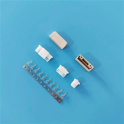
First, let’s ground this: a 1.20mm pitch connector refers to the distance between the center of one contact pin (or socket) and the next. That’s just 1.2 millimeters—about the thickness of two sheets of paper. Every pin and every socket is measured to exacting tolerances, so even a 0.1mm deviation can throw the whole connection off. I remember a customer last year, a medical device maker, who kept getting intermittent connection errors on their wearable heart monitors. Their team had already spent weeks checking firmware, screen displays, and battery modules, but it took a call to our engineering team to trace the problem back to their assembly process. They were applying too much force when crimping the connector’s wires, bending the socket pins just enough that half the contacts wouldn’t seat fully. That’s the kind of nuance you only pick up working with these parts day in and day out.
The most frequent issue we get called about is intermittent connections. This isn’t a total failure—your device turns on sometimes, cuts out when jostled, or works inconsistently after a week of use. For 1.20mm pitch connectors, intermittent problems almost always stem from three sources: poor mating alignment, contamination, or mechanical stress. Let’s break each down. Mating alignment is the biggest one here. Unlike larger pitch connectors, which have broad, easy-to-line-up guides, 1.20mm parts rely on small plastic housings or metal guide pins to keep pins and sockets aligned. If your assembly team doesn’t have the right tooling to insert the connector straight, they might seat it at a slight angle. Over time, that angle puts uneven pressure on the pins—one side bears too much force, the other not enough. The result: occasional signal drops when the component is moved. Our medical customer’s issue fell right here; they were using a manual crimp tool that didn’t provide uniform pressure across all 16 pins in their connector, so four of the sockets never made full contact. To fix that, we recommended switching to a pneumatic crimp press calibrated to apply exactly 15 pounds of force per crimp (a standard we’ve tested for our 1.20mm line) and adding a self-alignment jig during final mating. That cut their connection errors by 98% within a month.
Contamination is another silent culprit. Because the contact gaps in a 1.20mm connector are so small, even a speck of dust, flux residue from soldering, or a fingerprint’s oil film can bridge two adjacent pins or prevent a socket from making solid contact with a pin. We had a automotive client a few years back whose dashboard display would go blank randomly during test drives. Their initial thought was a software glitch, but when they sent a failing connector back to our lab, we found a thin layer of solder flux residue between the pins—leftover from wave soldering the PCB that never fully washed off. On the vibration of a moving car, that residue would shift, breaking the connection. Fixing this required a two-step cleaning process: a 10-minute soak in isopropyl alcohol (90% concentration, to avoid damaging the housing) followed by a 30-minute bake at 120°C to evaporate any leftover moisture. We also recommended adding a post-solder flux wash step to their assembly line, using a no-clean flux remover formulated for fine-pitch components. That’s a simple fix, but it’s easy to overlook when you’re focused on bigger assembly steps.
Mechanical stress, especially from repeated mating and unmating, or from improper mounting, is the third common cause. 1.20mm connectors aren’t meant to handle constant plugging and unplugging—they’re designed for one-time or low-cycle mating (usually 10 to 50 cycles, depending on the series). We had a consumer electronics brand that was using our 1.20mm connectors in their wireless headphones, and customers were complaining that the charging port connection would stop working after a month. Turns out, they were testing the charging port by plugging and unplugging it 100 times a day during product validation, which wore down the tiny gold plating on the socket contacts. The plating on our 1.20mm contacts is 3 microinches of hard gold, enough for 50 mating cycles, but not enough for high-cycle applications. We worked with them to switch to a series with 5 microinches of hard gold plating, which doubled the lifespan, and added a strain relief clip to the connector to take tension off the pins when the headphones were held or moved. That eliminated the wear issue. We also see mechanical stress from mounting: if the connector isn’t aligned properly on the PCB, the pins can bend under the weight of a thick component soldered on top. Our lab tests show that a 0.05mm bend in a single pin of a 1.20mm connector reduces current carrying capacity by 40%, and can cause intermittent connections.
Next, total connection failure. This is when your device won’t turn on at all, or has no power/signal through the connector. The two main causes here are soldering defects and mis-mating. Soldering defects are especially common in through-hole or surface-mount 1.20mm connectors. For surface-mount types, the small solder pads are only 0.6mm wide, so too much solder can cause a solder bridge between two adjacent pins. Too little solder, and the connection will be weak. We’ve seen assembly lines use too high a soldering temperature (over 260°C) which melts the plastic housing of the connector, warping the pins and making them impossible to seat. The fix here is to follow our recommended soldering profile: preheat the board to 150-180°C for 60-90 seconds, peak reflow temperature of 245°C max, and limit time above 230°C to 30 seconds or less. For through-hole connectors, the pin diameter is 0.4mm, so inserting the pin too far or not far enough can leave it below the solder pad. We always provide a dimensional drawing with our connectors that shows the exact insertion depth for through-hole pins, and we recommend using a stencil mask for surface-mount connectors to apply the right amount of solder paste (0.12mm thickness, to match the pad size).
Mis-mating is another big one for total failure. Some 1.20mm connectors have keyed housings to prevent backwards insertion, but if the key is damaged from rough handling during assembly, you can force the connector in wrong. When that happens, the pins and sockets don’t align, so none make contact. We had a client last year that was assembling 1,000 units a day, and 5% of them had non-working connectors. Their inspection team was missing minor cracks in the plastic keys, which let assemblers rotate the connector 180 degrees. Adding a visual check step during final inspection—counting the number of visible key features on the connector housing—cut that defect rate to near zero. Also, make sure you’re using the right connector mated to the right header. Some suppliers market “1.20mm pitch” parts with minor dimensional differences (like a 1.18mm vs 1.20mm center distance) that won’t mate properly. We always urge customers to source mating pairs from the same supplier, or to test the mating between different suppliers’ parts before full production, because even a 0.02mm difference can prevent a solid connection.
Now, how to test a 1.20mm connection when you’re not sure what’s wrong. We have a standard troubleshooting kit we send to customers for in-field testing, which includes a digital multimeter with a fine probe tip, a magnifying glass (10x magnification is non-negotiable for 1.20mm parts), isopropyl alcohol, and a plastic spudger (to avoid damaging pins). First, do a visual inspection: check for bent pins, cracked housings, or residue between contacts. Use the magnifying glass to look closely at each pin and socket—if a pin is bent, you can gently bend it back with the spudger (as long as it’s not cracked or broken). Next, test continuity: set your multimeter to the continuity setting, touch one probe to the pin on the PCB, and the other to the matching contact on the connector. If the multimeter doesn’t beep, that contact is not making a good connection. If multiple contacts fail, the issue is likely mis-mating or alignment. If only one or two fail, it’s probably a bent pin or soldering defect. We also recommend doing a mating force test: use a spring scale to measure the force needed to insert the connector. Our 1.20mm connectors require between 2 and 5 Newtons of force for full mating—if it takes more than 7 Newtons, there’s either debris in the housing or the connector is misaligned. For intermittent connections, a simple vibration test can help: gently tap the connector while testing continuity—if the connection drops when you tap it, that’s a sign of loose contacts or stress on the pins.
A common mistake we see customers make is over-tightening or under-tightening the connector’s locking mechanism. Many 1.20mm pitch connectors have latches or retention clips to hold them in place, and it’s easy to either push too hard and crack the latch, or not push hard enough to seat the connector fully. For example, in the automotive client I mentioned earlier, their assembly team was only pushing the latch halfway, so the connector wasn’t seated all the way, leading to intermittent connections on rough roads. We developed a simple “click test” for our connectors: you should feel two distinct clicks when mating, one for the initial seating of the pins, and a second for the latch engaging. That’s a quick, repeatable step that eliminates 30% of the connection issues we see from improper mating.
Another edge case: thermal expansion. 1.20mm pitch connectors are used in applications where temperatures can fluctuate widely, like industrial sensors that operate from -40°C to 125°C. The plastic housing and metal contacts expand and contract at different rates, which can cause pins to pull away from the PCB or contacts to lose tension. We test our connectors for thermal shock in our lab, cycling temperatures between -40°C and 125°C 100 times, but if your application is at the extreme end of that range, you might need a connector with a strain relief design that absorbs expansion. We had a wind energy customer whose turbine sensors were failing after a year of operation, and their issue was exactly thermal expansion—over time, the pins expanded too much, breaking the solder joint. We switched them to our 1.20mm series with integrated strain relief loops on the PCB pins, which let the pins expand without stressing the solder. That fixed their long-term failure rate.
If you’re still having trouble after going through these steps, it’s worth reaching out to a supplier with in-house testing capabilities, like our team. We’ve had customers send us faulty connectors, and in 80% of cases, we can identify the issue in 24 hours—whether it’s a manufacturing defect in the contact plating, a dimensional tolerance mismatch, or an assembly error. We even work with customers to adjust their assembly processes, like modifying crimp tools or adding cleaning steps, to prevent the issue from recurring. Our engineering team has worked on hundreds of 1.20mm pitch projects, from medical wearables to 5G base stations, so we know the nuances that generic troubleshooting guides often miss.
At the end of the day, 1.20mm pitch connectors are high-precision parts, and their tiny size means small errors have big consequences. The key to troubleshooting is to start with the simple checks: visual inspection, continuity testing, mating force, and cleaning, before moving to more complex fixes. And if you’re sourcing from a supplier, make sure you have access to engineering support that understands the specific needs of 1.20mm parts—off-the-shelf guides for larger connectors won’t always apply.

If you’re experiencing consistent issues with your 1.20mm pitch connections, or want to discuss optimizing your assembly process for better reliability, our team is ready to work with you to find a solution. Contact our sales team to discuss your project and request engineering support for your connection troubleshooting needs.
1.20mm Pitch References
- IPC-2221, Generic Standard on Printed Board Design. Institute for Printed Circuits, 2021.
- IPC-A-610, Acceptability of Electronic Assemblies. Institute for Printed Circuits, 2022.
- Molex Technical Bulletin TB-120mm-001: Design and Assembly Guidelines for Fine-Pitch Connectors. Molex LLC, 2023.
- TE Connectivity Application Note: Intermittent Connection Troubleshooting for Miniature Connectors. TE Connectivity, 2022.
Dongguan Yinglian Electronics Co., Ltd.
As one of the most professional 1.20mm pitch suppliers in China, we have world-leading production equipment and strong manufacturing capabilities. We warmly welcome you to buy bulk high quality 1.20mm pitch at competitive price from our factory.
Address: No.12, Jidele Road, Juqi, Humen Town, Dongguan City, Guangdong Province, P.R. China
E-mail: James@csg-china.com
WebSite: https://www.csg-conn.com/
